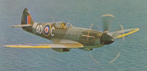
Here you find some Spitfire cockpit replica parts that I have made in recent years. They are made for static use for enthusiasts, cockpit builders, simulators and museum planes.
We are closing our production of the replica parts for cockpit enthusiast and we are offering significant discounts on remaining items.You can find some of these parts on the Spitfire Replica Cockpit Parts page.
If you have anything to ask about these items, please contact via Contact page.
Best regards, Harri
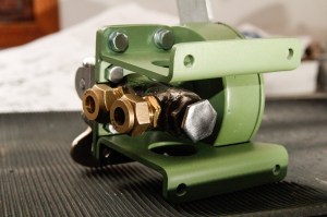
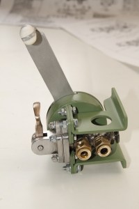
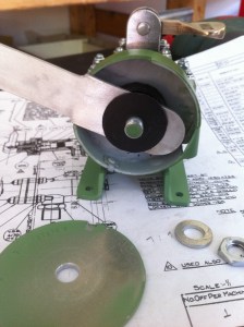
Replica Wobble Pump
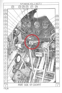
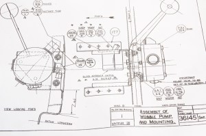
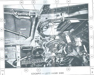
My latest item is Spitfire wobble pump. The pump situated starboardside of cockpit (see the image). A hand wobble pump was used on early Mk IX, XVI and XIV Spitfires for raising fuel pressure before starting the engine. On later aicrafts the pump was replaced by electric booster pump. The replica pump is made of steel and aluminium and is for static or display use only. A nice item in the cockpit sections or simulators.
We currently have one in stock. You can find it from Sales page.
Click on the images to enlarge them.


Spitfire door for simulator cockpits


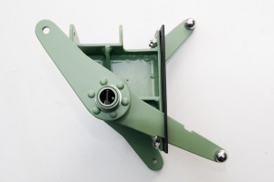
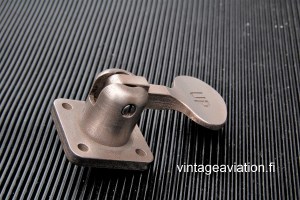
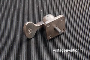
Flap Lever with Valve Body
The dummy valve body with separated rear pipe connection. The rear connection can be adjusted to the desired position like in the real one. We use BSP 1/4″ thread pipe connections.


Click on the images to enlarge them.
Undercarriage Pump for Mk I
The undercarriage pump was used in early Mk I Spitfires. Pumping the undercarriage up was awkward and often made the plane sway on takeoff. The pump was changed to a much more advanced control device during 1940 (see the U/C-control page down), but this is the right choice if you want to make exact copy from the early war Spitfire cockpit.
The replica pump is made of steel and aluminium. Levers are spring loaded and they feel like real ones. The LOWER – RAISE lever can be locked by pulling the knob and the large lever has a resistor that gives a sense of pumping motion. The pipe connection thread is BSP 1/4″. Except for a few details the pump is very faithful to the original device.


Click on the images to enlarge them.
Gyro Gunsight Mount
Gyro Gunsight, GGS, was fitted to the Spitfires IX, XVI and XIV. Our GGS mount for display use is made of 2 mm and 3 mm aluminium sheet. The bracket at the front is sheet metal. The steel boom is solid without vertical adjustement.


Click on the images to enlarge them.
Switch Bracket with labels
The bracket has different labels depending on the Spitfire mark. Here is one example.
")
")

Click on the images to enlarge them.
Mk I Throttle Quadrant early
The early Mk I quadrant is basically the same as used in the Mk II and Mk V but it doesn’t have an airscrew control box. The kind of quadrant was used in the 1939 and early 1940 Spitfires when they were equipped with different types of propeller.
")
")
")
")
Click on the images to enlarge them.
Mk II – V Throttle Quadrant
Quadrant with plastic airscrew box, boost cut-out lever, mixture lever, undercarriage master switch and a locking gear for friction gear. There is all but the horn switch. The levers are anodized aluminum and the texts are made with stickers. This is the most handsome looking Spitfire Throttle Quadrant of all.
")
")
")
")
Click on the images to enlarge them.
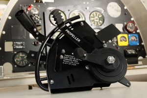
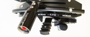
Mk IX and XVI Throttle Quadrant
The throttle lever gate give a slight friction as you are pushing the throttle lever to the combat power. The text AIRSCREW CONTROL is made with a sticker, the airscrew box is made of 3D plastic, the aluminium levers are anodized like the original ones.
")


Click on the images to enlarge them.
Mk IX Throttle Quadrant with Stand
The stand is made of aluminium and comes with the plate shown at the images.


")
Click on the images to enlarge them.
Throttle Quadrant Gear with Bracket
Spitfire Mk I – V quadrant shaft with two friction gears made of steel. The shaft, which has 25 mm thread, is welded to the lower bracket. This is the heart of the Spitfire quadrant and includes the most difficult parts to manufacture.
")
")
Click on the images to enlarge them.
Booster Cut Out Lever
Mk I – V Quadrants, made of steel. The text PUSH is sticker.
Click on the images to enlarge them.
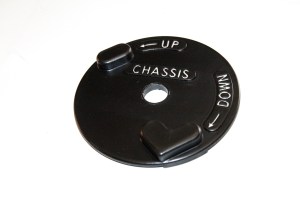
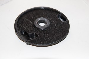
Undercarriage Control unit cover plate
The replica cover plate for the U/C unit. It is made of plastic and produced with 3D technology. The diameter of the pilot hole is 16 mm. It is designed for our nuts, but the hole can be drilled larger if required. We can supply the nut also.
Click on the images to enlarge them.
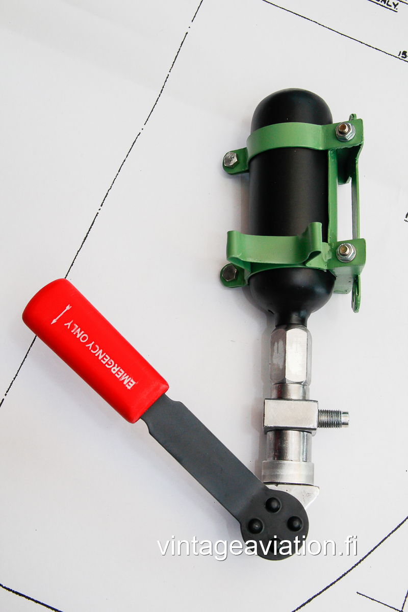
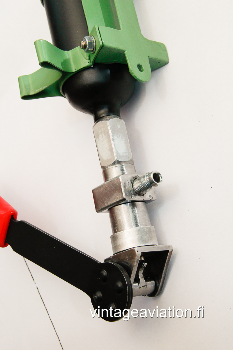
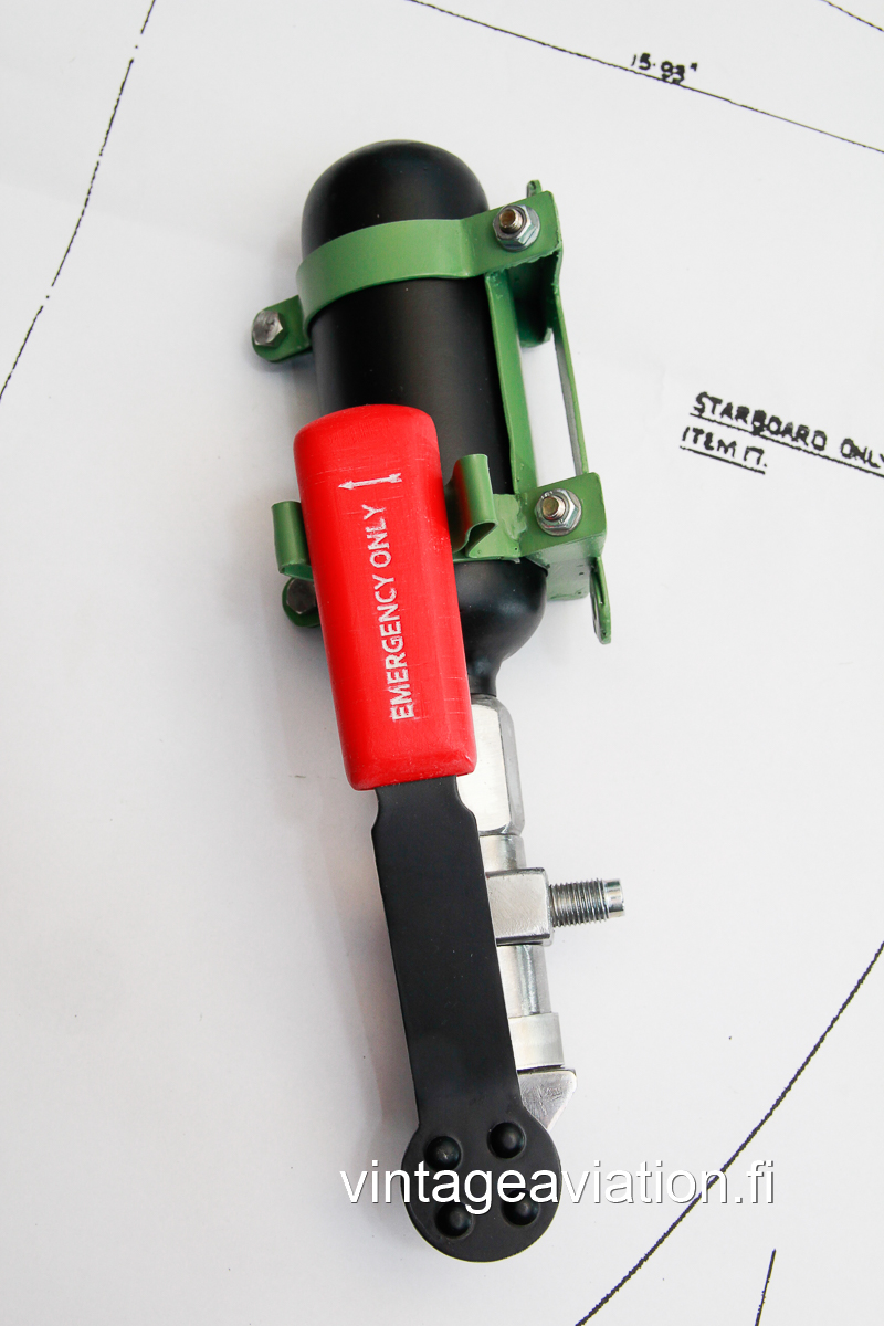
Chassis Emergency Unit
Unit with empty and closed replica bottle. All made of steel except the red handle which is plastic. The diameter of the bottle is 4,5 cm and the length about 13 cm. The pipe connection is 3/8″ x 24 UNF.
Click on the images to enlarge them.
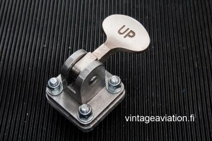
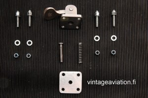
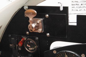
Mk I and II Landing Lamp Lowering Control
The unit was fitted left hand side below the instrument panel. This replica unit contains a dimmer lever and the UP/DOWN switch with valve body where the pipes can be fitted. The frame, the dimmer lever and the dimmer cup are made from aluminium. The switch with valve body is metal. I use BSP 1/4″ thread pipe connections.
Click on the images to enlarge them.
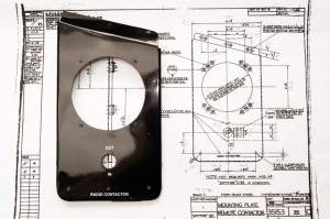
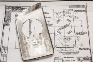
Remote Contactor Plate
The remote contactor was used most of the war time Spitfires from Mark II. The plate is made from aluminium according to the original drawings.

Click on the images to enlarge them.
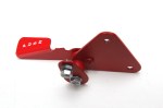
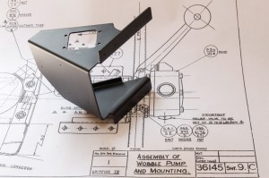
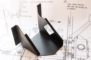
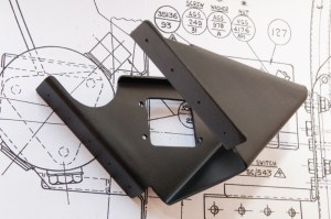
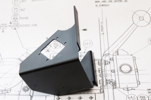
IX Wobble Pump Mounting Bracket
Black painted bracket made from aluminium according to the original drawings. The wobble pump was used in some Spitfire IX. The pump is located at the starboard side of the cockpit. The rivet holes and the pump mounting are marked in the bracket.
Click on the images to enlarge them.
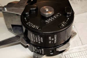
Undercarriage Control
The unit with the chain guard and two mounting brackets. The spring loaded lever moves and can be locked to up or down position. In this model the indicator doesn’t move – it shows IDLE all the time. The front plate and the knob are plastic. The valve block is made from metal, not the resin, like the reproductions usually are. That’s why I have made them with a rough metal surface and unpainted (like the lever also), so they feel like original ones, though the block was painted usually black, I think. The chain guard is made of aluminium sheet and the colour can be primer green or black. Pipe connections are BSP 3/8″.


Click on the images to enlarge them.
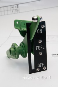
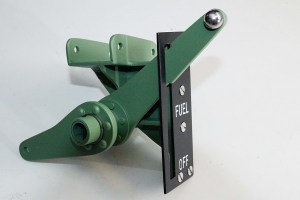
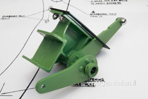
Fuel Cock Control, single lever
The single lever unit was used late Mk V onwards and was very common in the Spitfire IX and XVI. Unlike the original, the frame is welded from steel. The front shield is black anodized aluminum with an engraved text. The levers are made of 5 mm aluminium.
Click on the images to enlarge them.
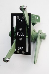
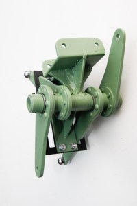
Fuel Cock, dual lever unit
Used in the Spitfire from Mk I to early Mk V. Unlike the original, the frame is welded from steel. The front shield is black anodized aluminium with an engraved text nad the levers are made of aluminium also, like in the original.
Click on the images to enlarge them.
Flap Control Lever, early
Used from Mk I to Mk V Spitfires.
The cam lever and the base are made of steel. Inside is a spring loaded piston made of steel. Inside of the unit is a spring loaded piston which is also made of steel. The spring loaded lever gives the feeling that it’s connected to the real valve.
Click on the images to enlarge them.
Flap Control Lever, late
Used in Spitfire Mk IX onwards. The cam lever and the base are made of steel. Inside of the unit is a spring loaded piston which is also made of steel. The spring loaded lever gives the feeling that it’s connected to the real valve.
Click on the images to enlarge them.
Mk XIV Throttle Quadrant
These large quadrants were used at late Spitfires. The body is made from 2 mm aluminium sheet. All aluminium parts are black anodized. Texts are made with stickers.

Click on the images to enlarge them.
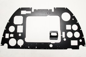
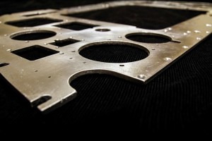
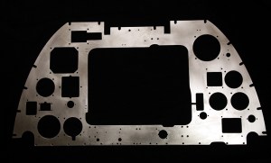
Spitfire Mk XIV instrument panel
The panel is made of 5 mm aluminium sheet.
Click on the images to enlarge them.

You must be logged in to post a comment.